Introduction to Computer Networks: Key Concepts and Basics
Imagine waking up in a world without the internet:
No way to instantly message your friends or see what’s trending on social media.
No ability to stream music, attend virtual classes, or play online games.
No quick access to information, collaboration tools, or even emailing for work or school.
Forget about video calls with loved ones across the world
Well, that's the world without computer networks.
Why Learn Computer Networks?
Simple answer: to do all the things we couldn’t do in a world without them.
Whether it’s browsing the web, sending messages, working remotely, streaming videos, or making video calls, computer networks are the backbone that make modern life seamless and connected. Every device—laptop, desktop, smartphone, smartwatch, or tablet—is a different form of a computer.
Regardless of your career path—whether you're a Software Development Engineer (SDE), Big Data Engineer, Network Engineer, or any other role in tech—understanding computer network fundamentals is essential.
Learning computer networks means understanding the hidden “plumbing” that powers our digital world.
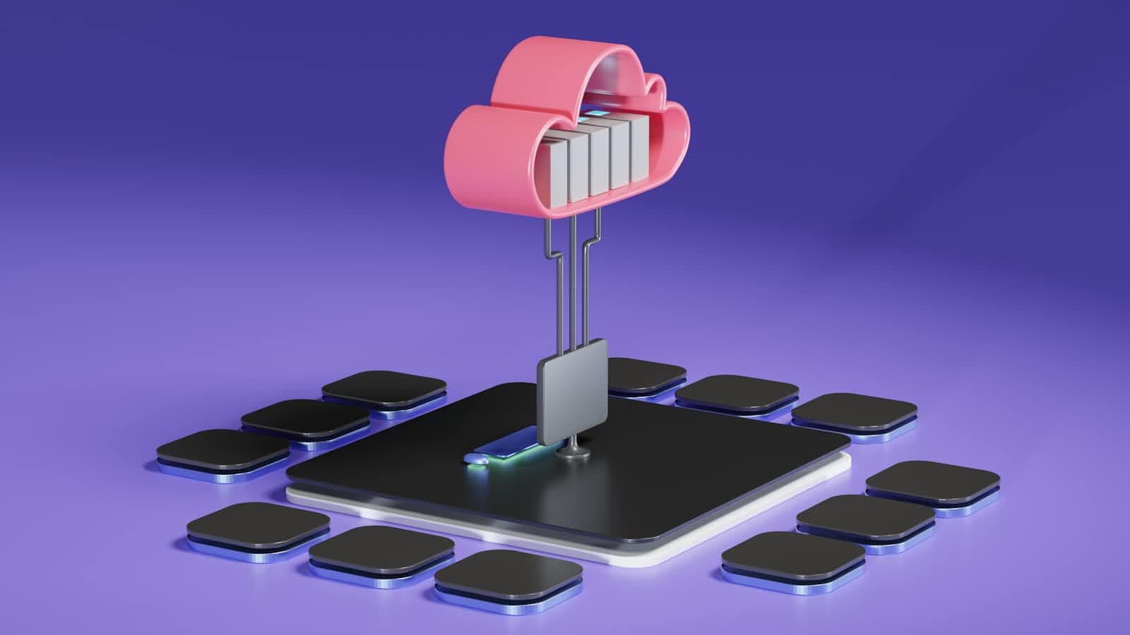
OSI Model ( Open-Systems-Interconnection )
Also referred to as a reference model, this model provides a high-level overview of how data is transmitted from one computer to another.

Anything that is a part of the network that wants to communicate is called a Host.
The server is a special type of computer. It is also a Host when receiving data from clients. The server is something that a host receives data from.
The OSI Model was finalized between the 1970s and 1980s. And it is a reference model, which means it acts as a reference guide to implement or form the network in the real world.
Based on the OSI model, the exact model that is implemented in the real world is the TCP/IP Model.
The OSI Model has 7 different layers. And each layer has a bunch of protocols that need to be followed to implement a network in the real world.
Protocols — A set of rules that everyone needs to agree upon.
Philosopher - Translator - Secretary Architecture
OSI model is based on the architecture of philosopher-translator-secretary.

In this architecture, there are two philosophers (A and B) in different locations, and they don’t speak the same language and want to transmit a message. So, some steps need to be followed by both to successfully send the message.
Philosopher A gives the message to his secretary, and the secretary will convert the message into a common language that can be understood by the secretary in both locations.
Then the converted message will be sent through Fax to Location B. And the secretary in location B will understand the message and pass it to the philosopher in the language the philosopher understands.
So, this way communication happens in this architecture. So, the same is followed in the OSI Model. Each layer states the different protocols that need to be followed for the successful transmission of the message.
Now, let’s look at the different layers in the OSI Model

Now, let’s briefly look at what each layer is,
Application Layer (Layer 7)
Browser → HTTPS / FTP (File Transfer Protocol)
Outlook → SMTP (Simple Mail Transfer Protocol)
Skype → Skype protocol
Remote Desktop → Telnet for Unix-based systems), RDP (Remote Desktop Protocol)
The application layer has a bunch of protocols that are used for various tasks. Outlook uses SMTP for mail transfers and HTTPS to fetch a web page securely.
Presentation Layer (Layer 6)
The presentation layer is mostly responsible for
Translation
Translates data received from the application layer into the form of ASCII or binarye.g
Data: Hello o ASCII: 72 101 108 108 111
Binary: 01001000 01100101 01101100 01101100 01101111
Data Compression
Suppose after translation we get 1MB of Data. So, Data Compression tries to reduce the size of the data without much loss because the less the size is the faster transmission can happen over the network.Encryption
Encrypts the data so that it can’t be misused. HTTPS uses SSL (Secure Socket Layer), which is a cryptographic protocol designed to provide communications security over a computer network.
Session Layer (Layer 5)
💡 These days, most modern browsers manage (Application, Presentation, Session layers)
Establish, manage, and terminate connections.
Establishment of a connection means making a connection in which both server and client have agreed to transfer the data.
Managing connection states, getting knowledge of the connections that were established, and the data transfer can be done effectively.
In terminating the connection, after the data transfer completes then the connection must be terminated.
Authentication and Authorization
Authentication: validation of the user ID and password
Authorization: whether a user has permission to access a file or not
An example of a session is a login and a logout
Transport Layer (Layer 4)
Segmentation
Data is broken into segments to transfer one chunk at a time, i.e., manageable. A general segment has Source IP, Destination IP, and Data (of the segment)
Flow Control
Managing the flow of data transmitted from one host to another host. The server is sending 10Mbps, but the host is not able to process. So, it requests the server to transmit 1Mbps transfer rate.
Error Control
There can be a loss of data or data might be corrupted. So, we use error control. These can be fixed in the Transport layer by something called Automatic Repeat Request (in case of loss of data receiver will ask to resend the data) or checksum (checks if the data is corrupted or not).
Network Layer (Layer 3)
The network layer’s main task is to recognize the network through which the data must be transmitted. It has something called packets. Each packet has a segment, which is received from the above layer and is encapsulated with a header in which we have source and destination addresses. We include the IP address in the TCP packet. Logical Addressing (IP Address).

What is an IP address?
Range of IP address: 0.0.0.0 to 255.255.255.255
It is the address that the network system has uniquely identified. It is a 32-bit or 4-byte address in IPv4, and each byte has an address range of 0-255, called an octet.
So, the task of the network layer is to provide the IP address to each host. And it also does Routing.
What is Routing?
The task of Routing is to route the packet from the source to the destination.
How do routers do that?
We have destination address it does Masking Masking is a simple bit wise operation. The router sets some bits to 0 and performs a bitwise AND operation, and after masking on the destination IP address, it will get the network IP address.
Now, with the help of the IP address, it will decide the next router for the packet it has to send.
DNS (Domain Name System) is used to connect a hostname like amazon.com to its IP address.
Data Link Layer (Layer 2)
The MAC Address is also called a physical address because it contains the address of the physical network device from which the data is going to be transmitted.
It is assigned to the network devices, such as NIC (Network Interface Card), Wi-Fi Card, USB Wi-Fi Dongle, etc., by the manufacturer.
The packet received from the network layer Data Link Layer encapsulates that with source and destination MAC addresses and creates something called, frame.

But Why MAC Address?
The MAC Address helps us to uniquely identify the device. If a packet is received, it helps us to determine which device it belongs to.
Apart from all these Data Link Layer does a few other things, such as
Access to Media: Media like (Copper wire, Fiber optic cable, Wireless). Since it has access to all these, it can detect Congestion, Error, Collision, etc.
Media Access Control
Media does not mean audio, video. Here, media means the medium through which the data is transferred. DLL helps to control the medium, such as when to transmit the data.- If Multiple hosts are connected to the same router, all the hosts cannot send packets at the same time. MAC ensures avoids collisions.

- Error Detection
It is added in the tail part; It is the mechanism to detect any error in the data. Some algorithms, like CRC (Cyclic redundancy check), Checksum, Bit Parity, etc., help us do that.
Physical Layer (Layer 1)
The physical layer deals with the encoding of the stream of bits into the signals. These signals are categorized based on the media (or medium).

The physical layer’s job is to transmit bits to a signal based on the medium used.
TCP vs UDP TCP UDP
| TCP | UDP |
|---|---|
| Slow, lossless | Fast, lossy |
| Feedback (whether the packet is received or not) | No feedback |
| Example: Email, Webpage | Example: Video call |
| Connection-oriented | Connection-less |
OSI Model vs TCP/IP